Hi all,
I am wondering if it is possible to make use of DMU Kinematics and Swept Volume (or something else) to simulate gear hobbing to model accurate gears. I know I can model gears in other ways, but I want to know if it is possible this way. In theory, if I can sweep the "Rack" correctly through the gear blank then the involute profile will be perfect.
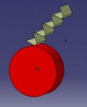
So far I have a sample Rack and Gear Blank, set up in a mechanism so that the rack Rolls around the gear blank correctly:

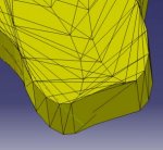
Then I can create a simulation/Replay of this and create a .model output of the swept path that the surface of the Rack takes. This is where the problem lies. This output Swept Volume is always in many many facets, so is therefore "steppy" and not suitable for simulating machining. Plus it seems REALLY HARD to generate useful CAD data from this .model file:


If I use the Trace command I can only pick edges or vertices...the output is nice (native at least) but again, not quite usable as a cutting profile. Below is output from pick 3 sides of a tooth:

Can anyone advise a better way to do this...or perhaps a way to clean up the .model ...or preferably a way to actually cut into the solid as the Rack sweeps through it (not stepped)?
Look forward to some ideas.
Thanks.
I am wondering if it is possible to make use of DMU Kinematics and Swept Volume (or something else) to simulate gear hobbing to model accurate gears. I know I can model gears in other ways, but I want to know if it is possible this way. In theory, if I can sweep the "Rack" correctly through the gear blank then the involute profile will be perfect.
So far I have a sample Rack and Gear Blank, set up in a mechanism so that the rack Rolls around the gear blank correctly:

Then I can create a simulation/Replay of this and create a .model output of the swept path that the surface of the Rack takes. This is where the problem lies. This output Swept Volume is always in many many facets, so is therefore "steppy" and not suitable for simulating machining. Plus it seems REALLY HARD to generate useful CAD data from this .model file:


If I use the Trace command I can only pick edges or vertices...the output is nice (native at least) but again, not quite usable as a cutting profile. Below is output from pick 3 sides of a tooth:

Can anyone advise a better way to do this...or perhaps a way to clean up the .model ...or preferably a way to actually cut into the solid as the Rack sweeps through it (not stepped)?
Look forward to some ideas.
Thanks.

